Composition and classification of diesel generators
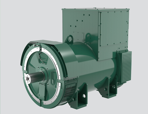
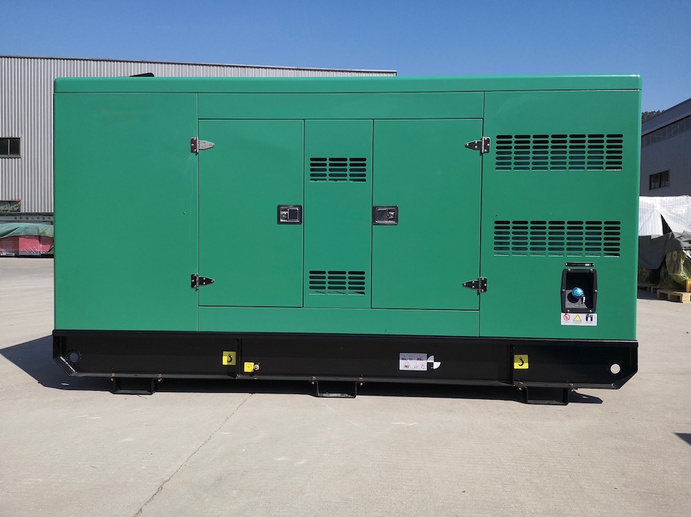
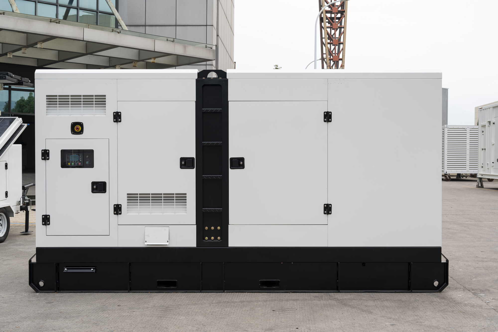
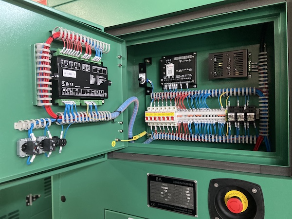
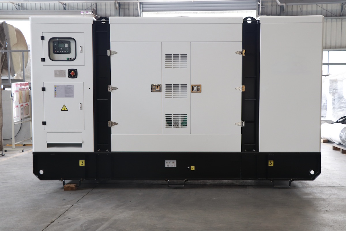
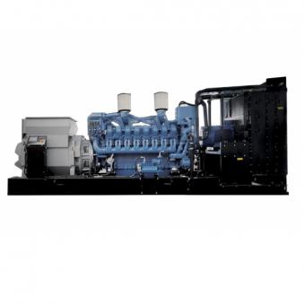
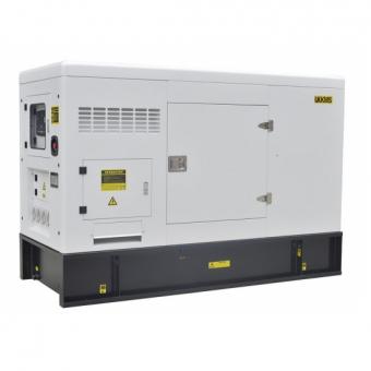
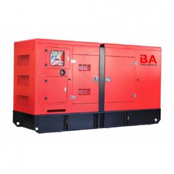
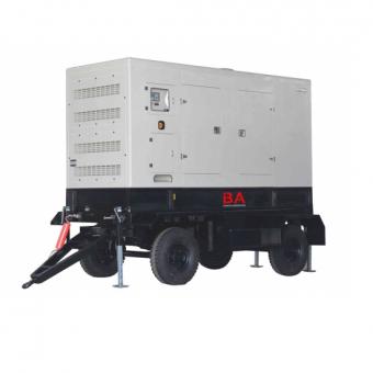
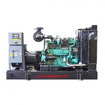
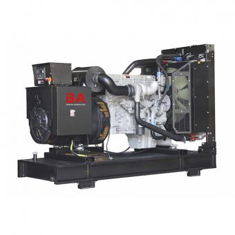
1. Composition and classification of diesel generators Diesel generator sets for AC power supply, backup and emergency power generation are widely used in many fields of the national economy such as ships and communications. In recent years, the power shortage caused by economic development and uneven resource distribution, especially in the southern coastal areas, has further highlighted the role of diesel generators in the development of the national economy. From hand-started and manned ordinary units to the direction of automation (self-starting, unattended, remote control, remote signaling, telemetry), low emissions and low noise, the technical equipment level of diesel generator sets is constantly improving. Modern diesel generator sets have the characteristics of flexibility, convenience, high degree of automation, low noise and low emissions. With the continuous development of science and technology, the application of some new technologies and new achievements has made modern diesel generator sets have higher intensification, reliability, stability and good emission characteristics, etc., and continue to meet the higher requirements of modern society. (1) Composition Diesel generator set is a type of internal combustion generator set, consisting of a diesel engine, a three-phase AC synchronous generator and a control system (including automatic detection, control and protection devices). The diesel engine, generator and control system (box) of the mobile diesel generator set are all assembled on a common base; while the diesel engine and generator of the larger power stationary unit are installed on a common base welded from steel, and Fixed on a specially designed reinforced concrete foundation, equipment such as the control system and fuel tank of this unit are usually installed separately from the unit. The flywheel housing of the diesel generator and the front end cover of the generator are directly connected in the axial direction using a shoulder positioning method to form an integrated body, and a cylindrical elastic coupling is used to directly drive the generator to rotate through the flywheel. This connection method is fixed together by screws, so that the two are connected into one body, ensuring that the concentricity of the crankshaft of the diesel engine and the rotor of the generator is within the specified range. In order to reduce the noise, diesel generator sets generally need to be installed with special mufflers. In special cases, the unit needs to be fully shielded. In order to reduce the vibration of the unit, shock absorbers or rubber shock absorbing pads are usually installed at the connections between the main components such as the diesel engine, generator, water tank and electrical control box and the public chassis. (2) Classification and functions There are many types of diesel generator sets, which can be divided into the following types according to their structural types, control methods and protection fun...
View More